As a rule, no jacking of the elevated railway structure was done while trains were passing over, and trains were flagged during the operation. There was generally very little delay, as all jacking was done between 10.30 A.M. and 2.30 P.M., when the traffic was lightest, and frequently the jacking was done between trains, causing no delay whatever. Steel clamps were placed, three on the top and three on the bottom of each set of the girders “C,” to bind them together and cause them to act as a unit.
All structures then being supported on girders “C,” which were carried on four concrete piers resting on the central rock core, the excavation on the sides of the avenue was continued down to sub-grade and the east and west portions of the concrete north abutment were constructed. The central rock core was about 36 ft. wide on the top and 45 ft. wide on the bottom, and at the center of 32d Street it was about 42 ft. high.
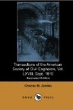
It was the original intention to excavate a sufficient width of the sides of the avenue to erect six rows of the permanent steel viaduct, 5 ft. from center to center, and this was done on the south portion of the work. On the north portion, however, the rock was of poor quality, and it was thought best to excavate for only five rows at first, to erect the five rows of permanent steel and put the timber bents in place under the ends of the girders “C,” in order to give them some support while the outside concrete piers were being removed and the excavation was being widened out to permit the erection of the sixth row. Additional raker braces were put in these bents temporarily, and were removed when the sixth row of steel had been erected. This is shown on Figs. 4 and 5.
[Illustration: PLATE XLVIII, FIG. 1.—TW 33, P.T. & T.R.R. Co. Terminal Station West. East side of 9th Ave. looking North from 31st St., showing rock excavation and supports of 9th Ave. structures. Dec. 28, 07.]
[Illustration: PLATE XLVIII, FIG. 2.—TW 39, P.T. & T.R.R. Co. Terminal Station West. East side of 9th Ave. looking North from 31st Street, showing rock excavation and permanent steel work. March 24, 08.]
[Illustration: PLATE XLVIII, FIG. 3.—TW 73, P.T. & T.R.R. Co. Terminal Station West. West side of Ninth Ave. Jacking up girders “C” at Elevated Railroad Column 491, showing method of taking weight on permanent viaduct girders. Nov. 14, 08.]
[Illustration: PLATE XLVIII, FIG. 4.—TW 58, P.T. & T.R.R. Co. Terminal Station West. East side of Ninth Ave. looking North from 31st St., showing underpinning of Ninth Ave. Structures. Aug. 10, 08.]
Fig. 4, Plate XLVII, and Fig. 1, Plate XLVIII, show the structures supported on the central rock core and the excavation on the east side to permit of the erection of the permanent viaduct girders. Fig. 1, Plate XLVIII, shows also the easterly portion of the concrete north abutment. Fig. 2, Plate XLVIII, shows five rows of the permanent viaduct girders erected on the east side of the work.


