The excavation of the sides of the avenue having been completed, and six rows of permanent viaduct girders erected on both sides, timber bents, as shown on Figs. 2, 4, 5, and 6, were erected on this steel to support the ends of the girders “C” and carry the structure while the rock core was being excavated. Fig. 3, Plate XLVIII, shows the method of taking the weight on these bents. Four 80-ton jacks were used, and oak blocks were placed on the top of each jack to transmit pressure to a temporary oak cap under the girders “C” independent of the bents; all four of these jacks were operated simultaneously, and the girders “C” were lifted off the bents and clear of the concrete piers. Oak filling pieces were then inserted between the bents and the girders “C,” so that when the jacks were released the girders “C” were clear of the concrete piers. Fig. 3, Plate XLVIII, shows that the girders have been lifted off the piers. Elevations were taken on each set of girders during each operation, and careful observations were made on the elevated railway columns. Where the rock was very close to these bents, the open space between the posts was filled with blocking so that there would be less danger of the bent shifting if struck by blasted materials. Fig. 3, Plate XLVIII, shows one of these bents filled with blocking.
All structures being carried on girders “C,” which, in turn, were carried on the sides of the permanent viaduct, the central core was excavated. Fig. 4, Plate XLVIII, and Figs. 1, 2, 3, and 4, Plate XLIX, show various views of the work at this stage.
The central portion of the viaduct was then erected, and, using concrete piers and timber bents, all structures were placed on its deck. Fig. 3, Plate XLIX, shows the piers under the elevated railway columns prior to the removal of girders “C.”
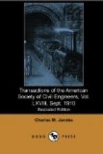
[Illustration: FIG. 6. (Full page image)
GENERAL ARRANGEMENT OF TEMPORARY AND PERMANENT STRUCTURES]
During the latter part of 1908 a 48-in. cast-iron water main was laid by the city on a cradle built by the Railroad Company on girders “C” on the east side of the avenue. This is part of the high-pressure system, and the location and elevation of this water main were taken into consideration when the underpinning was designed. This main, and the 48-in. cast-iron sewer bracketed to girders “C,” are shown on Fig. 4, Plate XLVIII.
Elevations had been taken on marks on the elevated railway columns between 30th and 34th Streets at the time the original surveys were made, in 1902, and these marks were used to test the level of the structure during the progress of the excavation.


