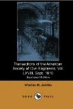
It was decided, however, that, inasmuch as the cracks did not affect the stability of the walls, the increased cost of thus reinforcing the remaining walls was not warranted. An effort to control the cracks was made by placing corrugated-iron diaphragms in the form, dividing each 50-ft. section into three parts. The diaphragms were 1 ft. wide, and were placed with the outer edge 1 in. in from the face of the wall, but in the copings they were omitted. The purpose of these diaphragms was to provide weak sections in the walls, so that if there was any tendency to crack it would occur along the line of the diaphragms. Corrugated iron was used for the diaphragms instead of sheet iron as it was more easily maintained in a vertical position. The general arrangement of the diaphragms is shown on Fig. 4, Plate LII. The results obtained by using diaphragms have been quite satisfactory, and cracks approximately straight and vertical have usually appeared opposite the diaphragms soon after the forms were removed. Diaphragms were used on all the remaining walls, with the exception of those between Stations 187 + 07 and 188 + 83 on the north side, where the rock was of poor character and bad slides had occurred. Between these points, in order to strengthen the wall, twisted steel rods, 1 in. square, were placed longitudinally, 6 in. in from the face of the wall and 2 ft. apart vertically, between Elevations 295 and 335.
[Illustration: PLATE LII, FIG. 1.—GIRDERS UNDER 9TH AVENUE ELEVATED RAILROAD.]
[Illustration: PLATE LII, FIG. 2.—TW 100. P.T. & T.R.R. Co. Terminal Station West. Showing excavation of completion of South abutment 9th Ave. and method of Supporting Elevated Railway Column 488. July 21, 09.]
[Illustration: PLATE LII, FIG. 3.—TW 31. P.T. & T.R.R. Co. Terminal Station West. View showing excavation 9th and 10th Avenues South of 32nd St. looking West from Sta. 184. Aug. 17, 07.]
[Illustration: PLATE LII, FIG. 4.—TW 101. P.T. & T.R.R. Co. Terminal Station West. Inside of concrete form for lower-face wall, showing drains, tie rods, diaphragms and methods employed for tying in the form in addition to braces outside. July 21, 09.]
Tenth Avenue Portal.—The design of the Tenth Avenue Portal is shown on Fig. 9. The stone selected came from the Millstone Granite Company’s Quarries, Millstone Point, Conn., and is a close-grained granite. Fig. 2, Plate LI, shows the completed portal.
Practically all the stone cutting was done at the quarry, but certain stones in each course were sent long and were cut on the ground, in order to make proper closures. Drains were left behind the portal around the back of each arch, leading down to the bottom, and through the concrete base at each side of the portal and in the central core-wall; all these drains have been discharging water.


