The system will be understood from figure 77, where L is the overhead conductor joined to the positive pole of the dynamo or generator in the power house, and C is a rolling contact or trolley wheel travelling with the car and connected by the wire W to an electric motor M under the car, and geared to the axles. After passing through the motor the current escapes to the rail R by a brush or sliding contact C’, and so returns to the negative pole of the generator. A very general way is to allow the return current to escape to the rails through the wheels. Many tramways, covering thousands of miles, are now worked on this plan in the United States. At Bangor, Maine, a modification of it is in use whereby the conductor is divided into sections, alternately connected to the positive and negative poles of two generators, coupled together as in the “three-wire system” of electric lighting (page 119), their middle poles being joined to the earth —that is to say, the rails. It enables two cars to be run on the same line at once, and with a considerable saving of copper.
To make the car independent of the conductor L for a short time, as in switching, a battery of accumulators B may be added and charged from the conductor, so that when the motor is disconnected from the conductor, the discharge from the accumulator may still work it and drive the wheels.
Attempts have been made to run tramcars with the electricity supplied by accumulators alone, but the system is not economical owing to the dead weight of the cells, and the periodical trouble of recharging them at the generating station.
On heavy railroads worked by electricity the overhead conductor is replaced by a third rail along the middle of the track, and insulated from the ground In another system the middle conductor is buried underground, and the current is tapped at intervals by the motor connecting with it for a moment by means of spring contacts as the car travels In each case, however, the outer rails serve as the return conductors
Another system puts one or both the conductors in a conduit underground, the trolley pole entering through a narrow slot similar to that used on cable roads
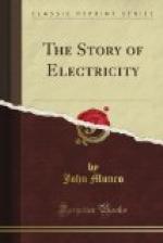
The first electric carriages for ordinary roads were constructed in 1889 by Mr. Magnus Volk of Brighton. Figure 78 represents one of these made for the Sultan of Turkey, and propelled by a one-horse-power Immisch electric motor, geared to one of the hind wheels by means of a chain. The current for the motor was supplied by thirty “EPS” accumulators stowed in the body of the vehicle, and of sufficient power to give a speed of ten miles an hour. The driver steers with a hand lever as shown, and controls the speed by a switch in front of him.
Vans, bath chairs, and tricycles are also driven by electric motors, but the weight of the battery is a drawback to their use.


