The trestle east of the steel structure at Eleventh Avenue had simple four-post bents, as shown by Bent “A,” on Fig. 5, all posts being vertical, to save room at the street level; the outside posts and the caps and sills were of 12 by 12-in. timber; the intermediate posts were of 8 by 12-in. timber; and single or double decks of 3 by 8-in. bracing were used, depending on the height of the bents. These bents were framed on the ground in position and raised by hand. West of Tenth Avenue, the sills of the bents rested on four 12 by 12-in. longitudinal timbers, each spanning two bays and breaking joints, for convenience in supporting the trestle while the tunnels were constructed in open cut beneath. These bents were placed 12 ft. on centers, with one 8 by 16-in. stringer under each rail, and one 6 by 16-in. jack-stringer supporting the overhang of the floor on either side.
The bents along the New York Central freight shed had but two posts of 12 by 14-in. yellow pine varying from 26 ft, to 31 ft. 9 in. from center to center; they had double caps of 12 by 14-in. yellow pine on edge, no bottom sills or bracing, and the vibration and wind pressure were taken care of by the top bracing and anchorage, as shown by Bent “G,” on Fig. 6.
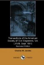
[Illustration:
Fig. 4.
PLANT FOR DISPOSAL OF EXCAVATED MATERIALS
PIER NO. 72 N.R.]
The method of erection was as follows: An excavation was made on the line of each post, 4 ft. deep and from 4 to 5 ft. square, depending on whether it was for a single or reinforced post; 6 in. of concrete was placed in the bottom, and on this were laid, at right angles to the center of the trench, three 8 by 12-in. timbers varying in length with the excavation from 3 to 4 ft. To these timbers was drifted one 12 by 12-in. timber of the same length as those in the bottom row, but at right angles to them. Elevations were then taken on top of the 12 by 12-in. timber, and the bent was framed complete and of correct height. The framing was done south of the line of the trestle and west of the freight-house. The framed bents were picked up by a small two-boom traveler carrying two double-drum, electric, hoisting engines, and run forward into position. A hole had previously been made in the metal gutter and canopy of the freight-house, by an experienced roofer, and in the freight platform underneath, and, as soon as the bent had been dropped into position, it was firmly drifted to the foot-blocks, previously described, and the excavation made for them was filled with concrete


