Street Surface.—It was the original intention to close and excavate the east side of the avenue and to erect there a street-traffic trestle before closing the west side, but, at the contractor’s request, both sides were closed, and all vehicular traffic was turned into the center. A light trestle on the west side of the avenue provided for pedestrian traffic.
Other Sub-surface Structures.—There were various gas mains, water mains, electric conduits, manholes, hydrants, etc., in the avenue, and most of these were cut out temporarily, at the contractor’s request, to be replaced subsequently.
Supports for Elevated Railway Structure.—As stated previously, the central track had to be supported independently.
The overhead girders, known as girders “B”, were therefore designed as shown on Fig. 1, and put in place as shown on Figs. 2 and 3. The outside tracks were blocked directly on these girders, and the central track was supported by blocking up the transverse girders on I-beams placed between the girders “B”; and no blocking was placed between the girders “B” and the longitudinal girders carrying the central track. The weight on each column was assumed to be 172,000 lb.
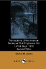
[Illustration: FIG. 1. (Full page image)
DETAILS OF STEEL GIRDERS, ETC. SUPPORTING NINTH AVENUE STRUCTURES]
Supports for Surface Railway Structure.—A uniform load of 3,000 lb. per lin. ft. of single track, with the weight of a car at 39,000 lb., was assumed. Several feet of earth, between the structure and the rock, were mined out, and the structure was supported on I-beams and posts, and ultimately on the transverse girders by using timber bents under the I-beams, as shown on Fig. 3.
Water Mains and Sewer.—Cradles were designed for the support of the 48-in. and 24-in. water mains, resting on the transverse girders, and the 48-in. cast-iron sewer on the east side of the avenue was carried on I-beams bracketed to the ends of the transverse girders, as shown on Figs. 1 and 2.
[Illustration: FIG. 2. (Full page image)
METHOD OF SUPPORTING ELEVATED RAILWAY STRUCTURE]
[Illustration: FIG. 3. (Full page image)
METHOD OF SUPPORTING TRACKS OF NEW YORK CITY RAILWAY CO.]
Girders “C."—The transverse girders below the street surface, referred to above, were known as girders “C,” and they were put in place at first resting on concrete piers on the central core; the weight of all structures was placed on them while the sides of the avenue were being excavated, and the sides of the viaduct were being built. The ends of these girders were then picked up on the sides of the viaduct, and, spanning the central rock core, carried all structures while the core was being excavated and the viaduct completed. New foundations were then placed on the deck of the viaduct to carry all structures.
Fifty-four of these girders were required, each weighing about 19,000 lb. The bents carrying the ends of these girders on the sides of the viaduct are shown on Fig. 2. They were of long-leaf yellow pine. These girders were located so that a cradle could be laid on them east of the elevated railway structure to carry a proposed 48-in. cast-iron water main.


