Transactions of the American Society of Civil Engineers, vol. LXVIII, Sept. 1910 eBook

This eBook from the Gutenberg Project consists of approximately 43 pages of information about Transactions of the American Society of Civil Engineers, vol. LXVIII, Sept. 1910.

Transactions of the American Society of Civil Engineers, vol. LXVIII, Sept. 1910 eBook

This eBook from the Gutenberg Project consists of approximately 43 pages of information about Transactions of the American Society of Civil Engineers, vol. LXVIII, Sept. 1910.
not be necessary to use raker braces against it.  This would have been desirable, as the placing of the raker braces took considerable time.  It was found, however, that the form was not sufficiently rigid, as it bulged at the middle section and could not be held by the trusses.  Two or three sets of raker braces, about 12 ft. apart, were used, and in addition, rods with turnbuckles were placed through the form and fastened to the tie-rods, and thus the form was held in place successfully.  On the forms built later, the trusses were omitted, and raker braces, about every 6 ft., were used.  The rods which screwed into the turnbuckles were removed before the form was moved.  The photograph, Fig. 4, Plate LII, was taken inside the concrete form for the lower face wall on the north side, and shows the drains leading through the wall, the turnbuckles attached to the tie-rods, the cables attached to rods in the rock, and the braces to keep the form from coming in; these braces, of course, were removed as the concrete came up.  The form was built low and wedged up into position.  After a section of concrete had set sufficiently, the wedges were knocked out, the form was lowered and moved from the wall, and was then moved along the lowest waling piece by block and tackle to its new position.

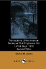
Fig. 4, Plate L, shows the forms used on the north side of the work.

A section, 1 ft. square, at the top of the bridge seat of the lower face wall, was left out, so that the bottom of the form for the upper face wall could be braced against it.  The top of this form was tied by cables attached to rods in the rock and by rods with turnbuckles running from back to front of the form; braces were also put in from the back of the retaining wall form to the walls of buildings along the property lines, when this could be done.  The middle section of the form was held by rods with turnbuckles which passed through the form and were fastened to each of the tie-rods drilled into the rock, as was also done in the case of the lower face wall.  It was generally possible to hold the form to true position in this manner, but occasionally it had a tendency to bulge; when this occurred, the rods leading through the form and fastened to the tie-rods were tightened up, the placing of the concrete was slowed up, and no serious bulging occurred.

Bulkheads at the ends of the sections were built of rough planking securely braced to the rock, except that a planed board was laid up against the face of the form to make a straight joint.  At the end of each section a V was formed, as shown by Fig. 1, Plate LI.  At all corners, a “return,” or portion of the wall running at right angles, was built, and no section of wall was stopped at a corner.

Copyrights
Project Gutenberg
Transactions of the American Society of Civil Engineers, vol. LXVIII, Sept. 1910 from Project Gutenberg. Public domain.