No blasting was done near the supports of the elevated railway structure while trains were passing over it, and occasionally trains were stopped during a heavy or uncertain blast. A watchman on the surface, day and night, and at first one and later two flagmen on the elevated railway structure, were on duty at all times, reporting to the Interborough Rapid Transit Company, by whom they were employed. Log mats and timber protection for the girders and the columns of the permanent viaduct were used, as shown by Figs. 1 and 4, Plate XLIX, during the excavation of the rock core, and timber was also used to protect the face of the completed portions of the concrete abutments.
In excavating the sides of the avenue, the rock broke better on the east than on the west side, where large seams developed and some slides occurred.
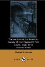
Abutments.—As shown on Fig. 7, the face of the north abutment has a batter of 2 in. to the foot, and the face of the south abutment has a variable batter, the base being on a grade and the bridge seat being level, and both maintaining a uniform distance from the center of the Terminal Yard. The back walls of the abutments were not built until the steel had been put in place.
No attempt was made to water-proof these abutments, but, in the rear of the wall, open spaces were left, about 6 ft. from center to center, which were connected with drain pipes at the base of and extending through the wall, for the purpose of carrying off any water that might develop in the rock. These drains were formed by building wooden boxes with the side toward the rock open and the joints in the boxes and against the rock plastered with mortar in advance of the wall. A hose was used to run water through these drains during the placing of the concrete, for the purpose of washing out any grout which might run into them. Each box was washed out at frequent intervals, and there was no clogging of the drains whatever. This method of keeping the drains open was adopted and used successfully for the entire work. The abutments were built of concrete, and the mixture was 1 part of cement, 3 parts of sand, and 6 parts of broken stone.
The concrete was mixed in a No. 3 Ransome mixer, and was placed very wet. No facing mixture or facing diaphragms were used, but the stone was spaded away from the face of the wall as the concrete was laid. Chutes were used inside the form, if the concrete had to drop some distance. Work was continued day and night, without any intermission, from the time of commencement to the time of completion of each section.


