We will now describe the manner in which this principle has been realized in the practical construction of both a thermo-magnetic generator and motor.
[Illustration: Fig. 1.]
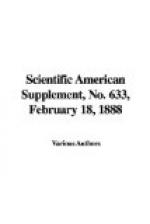
Fig. 1 shows an elevation and part section of one of the arrangements employed. Fig. 2 is a plan of the same machine (in the latter the ring, a a, appearing on a higher plane than it actually occupies).
[Illustration: Fig. 2.]
N S is an electro-magnet, a a the armature, wound as a Gramme ring, and fixed to a frame with four arms, which can turn freely upon a pivot midway between the poles. The cross arms of the frame are attached at 1, 2, 3, 4, Fig. 2. Between the magnets and the armature is placed the distributor, d d, where it occupies an annular space open above and below. Both the magnets and the armature are coated on the sides facing the distributor with mica or some other non-conductor of heat and electricity. The distributor is attached to and supported by the cross arms, so that it turns with the armature.
The distributor is composed of a ribbon of iron or nickel, bent into a continuous zigzag. This form has the advantage of presenting, in the cool part of the distributor, an almost direct road for the lines of force between the poles and the armature, thus diminishing the magnetic resistance as far as possible. At the same time the Foucault currents are minimized. To the same end it is useful to slit the ribbon, as in Fig. 3. This also facilitates the folding into zigzags.
[Illustration: Fig. 3.]
The distributor is heated at two opposite points on a diameter by the burners, b b, above which are the chimneys, e e. The cooling of the alternate section is aided by the circulation of cold air, which is effected by means of the draught in the chimneys, e e. At the points of lowest temperature a jet of air or water is maintained. The cross arms are insulated with mica or asbestos at the points where they extend from the armature to the distributor.
It will now be evident that while the distributor is entirely cool, many of the lines of force pass from N to S without entering the armature core; but if heat is applied at the points 1 and 2 in the figure, so as to increase the magnetic resistance at these points, then a great portion of the lines will leave the distributor, and pass through the armature core. Under these conditions, so long as heat is applied at two points equidistant from N and S, we might, if we so pleased, cause the armature to be rotated by an external source of power, and we should then have an E.M.F. generated in the armature coils—that is to say, the machine would work as an ordinary dynamo, and the power expended in driving the armature would be proportionate to the output.


