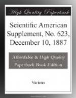
Fig. 1 represents the apparatus in section. The steam enters through the tubulure, A, and finds its way around the periphery of a tuyere, D. It escapes with great velocity, carries along the petroleum that runs from two lateral tubulures, B (Fig. 2), and throws it in a fine spray into the fireplace, through the nozzle, C (Fig. 1), which is flattened into the shape of a fan opened out horizontally. The mixture at once ignites in contact with the hot gases, and gives a beautiful, long, clear flame. The air necessary for the combustion is sucked through the interior of the nozzle, H, which is in front of the tuyere. It will be seen that the current of steam can be regulated by moving the tuyere, D, from or toward the eduction orifice. This is effected through a maneuver of the hand wheel, F. In the second place, the flow of the petroleum is made regular by revolving the hand wheel, G, which gives the piston, O, a to and fro motion in the tuyere, D.
[Illustration: FIG. 1—THE DIETRICH PETROLEUM BURNER.]
The regulation may be performed with the greatest ease. It is possible to instantly vary, together or separately, the steam and the petroleum. Under such circumstances, choking is not to be feared at the petroleum orifice, where, according to experiment, the thickness of the substance to be vaporized should not be less than 0.04 of an inch.
The petroleum might evidently be made to enter at A and the steam at B; but one of the conclusions of the experiments cited is that the performance is better when the jet of steam surrounds the petroleum. It will be understood, in fact, that by this means not a particle of the liquid can escape vaporization and, consequently, combustion. Moreover, as the jet of petroleum is completely surrounded by steam its flow can be increased within the widest limits, and this, in certain cases, may prevent an obstruction without much diminishing the useful effect of the burner.
The apparatus is easily and rapidly taken apart. It it is only necessary to remove the nozzle, C, in order to partially clean it. It would even seem that the cleaning might be done automatically by occasionally reversing the flow of the steam and petroleum. However efficacious such a method might prove, the apparatus as we have described it can be very easily applied to any generator. Fig. 2 represents it as applied to the front of a furnace provided with two doors. A metallic box, with two compartments, is placed on one side of the furnace, and is provided with two stuffing boxes that are capable of revolving around the steam and petroleum pipes. The latter thus form the pivots of the hinge that allows of the play of the vaporizers and piping.
[Illustration: FIG. 2—THE BURNER APPLIED TO THE FURNACE OF A BOILER.]
It was in this way that Mr. Dietrich arranged his apparatus in an experiment made upon a stationary boiler belonging to a Mr. Corpet. The experiment was satisfactory and led to the adoption of the arrangement shown in Fig. 3. The fire bridge is constructed of refractory bricks, and the majority of the grate bars are filled in with brick. The few free bars permit of the firing of the boiler and of access of air to the interior of the fire box. Under such circumstances, the combustion is very regular, the furnace does not roar, and the smoke-consuming qualities are perfect.


