2240 x 24 x 1000
of 24” x 10”--whence W = ---------------- = 165925 lbs.,
324
[TeX: $W = \frac{2240 \times 24 \times 1000}{324} = 165925$]
and as 134400 lbs. was all that the conditions demand, we really have an excess of strength. The next set of braces supports the weight of the rectangle included between the upper ends of the braces and the two chords, and the dimensions of the sticks are calculated in the same manner. We find, as we approach the centre of the bridge, that the strains on the braces become less, and consequently their scantling should be reduced, but in ordinary practice this is seldom done.
=Rods.= The next thing is to ascertain the dimensions of the various tie rods. It is evident that the same weight comes upon the first set of rods, as on the first set of braces—which will give for the rods at one end of one truss, 134400 lbs.; and as there are two of these rods, each will sustain a strain of 67200 lbs.—and, at 15,000 lbs. per square inch, will have an area of 4.48 sq. inches, and, by Vose’s Tables, must have a diameter of 2-1/2 inches. The sizes of the rods in each set will decrease towards the centre of the bridge as the weight becomes less.
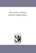
[Illustration: Pl. II. with Fig. 1., Fig. 2., Fig. 3., Fig. 4.]
=Counterbraces.= Now, as to the necessity of Counterbracing, there are various opinions. The object of it is to stiffen the truss and check vibrations. If a load be placed over any panel point, it causes that portion of the truss to sink, and produces an elevation of the corresponding panel point at the other end of the truss—thus producing a distortion, which change of form is resisted by proper counterbraces. The strain to which this timber is subjected is caused by the moving load on one panel only—and requires only scantling of the size of the middle braces. These counterbraces should not be pinned or bolted to the braces where the cross—as their action is thereby entirely altered—but it is well to so confine them as to prevent vertical or lateral motion.
=Shoes.= Formerly it was the custom to foot the braces and counters on hard wood blocks on one side of the chord, the vertical rods passing through and screwing against a block on the other side—thus the whole strain tended to crush the chord across its fibres. This is now remedied by the use of cast iron blocks, bearing on one side of the chord, but having tubes extending through to the other side, where the washer plate for the bolts fits firmly on their ends, forming a complete protection, as all the crushing strain is received on the block itself.
=Width.= It now becomes necessary to determine upon the width between the two trusses. For a single track bridge for a railroad, 14 ft. is the usual width adopted, and for a highway bridge, from 12 to 16 ft. When a double track is required, three trusses are usually employed, with a width for each roadway of 14 ft. for railroads.


