in the form of spray plays on the tubes, T, and absorbing
any residual heat. The heat generated by compression
in the cylinder, C, is absorbed by a spray of water
from the pump, H, the vapor being carried along with
the air through the pipe, R, to the chamber, Y, where
it is separated, and falling to the bottom is circulated,
as just described, by the pump, J. X is a small auxiliary
air compressor, to obtain the necessary compression
to start the engine, and is worked from the boiler,
W. In future engines this compressor will be superseded
by a specially designed injector, which will produce
the necessary pressure at a considerable reduction
in cost. When once the engine is started, the
fire of the auxiliary boiler can, of course, be drawn,
as the main engine afterward makes its own steam.
The regenerator, E, has circular ends of fire clay
perforated, the body being filled with fire clay spirals
of the shape clearly shown in elevation in Fig. 2.
The injector valve for the creosote is shown to a
larger scale in Fig. 3. This valve has, however,
been since considerably modified and improved.
The feed and exhaust valves, M, are actuated by cams
keyed to a countershaft driven by bevel wheels from
the main shaft. The creosote pump, F, is also
worked by a cam on the same shaft, but the pumps, G
H J, are worked by eccentrics. A stop valve,
N, is fixed to the supply pipe, P, under which is
place a back pressure valve to retain the pressure
in the combustion chamber. The engine is regulated
by an ordinary Porter governor actuating the throttle
valve, O. An engine, as described, has been constructed
by Messrs. Adair & Co., engineers, Waterloo Road,
Liverpool, and has been running most satisfactorily
for several weeks, the results being clearly shown
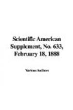
by the indicator diagrams (Figs. 5 and 6). The
results obtained by this motor are very remarkable,
and are a long way in advance of any previous performance,
as only a little over 1/2 lb. of fuel is used per
i.h.p. per hour. It may be mentioned that the
temperature of the combustion chamber is calculated
to be about 2,500 deg.F., and that of the exhaust
gases does not exceed 180 deg.F.—Industries.
[Illustration: Diagram from cylinder—25 in. diam, 18 in. stroke. I.H.P., 63. Scale, 1/30 in. Mean pressure, 28.2 lb. Fig. 5.]
[Illustration: Diagram from air pump—15 in. diam., 18 in. stroke. I.H.P., 23. Scale, 1/30 in—Mean pressure, 28.5 lb. Fig. 6.
Diagrams from cylinder and air pump.
Net indicated horse power, 40; revolutions per minute, 100; coal tar consumed per hour, 20.5 lb.; coal tar per I.H.P. per hour, 0.512 lb.]
* * * * *
AN INVESTIGATION INTO THE INTERNAL STRESSES OCCURRING IN CAST IRON AND STEEL.
By general Nicholas KALAKOUTZKY.
NO. I.


