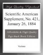
Prof. Zenger likewise had on exhibition a “Universal Electrometer” (Fig. 2), in which the fine wire that served as an electrometric needle was of magnetized steel suspended by a cotton thread. In this instrument, a silver wire, t, terminating in a ball, is fixed to a support, C, hanging from a brass disk, P, placed upon the glass case of the apparatus. It will be seen that if we bring an electrified body near the disk, P, a deviation of the needle will occur. The sensitiveness of the latter may be regulated by a magnetic system like that of the galvanometer. Finally, a disk, P’, which may be slid up and down its support, permits of the instrument being used as a condensing electrometer, by giving it, according to the distance of the disks, different degrees of sensitiveness. One constructor who furnished much to this part of the exhibition was Mr. Th. Edelmann of Munich, whose apparatus are represented in a group in Fig. 3. Among them we remark the following: A quadrant electrometer (Fig. 4), in which the horizontal 8-shaped needle is replaced by two connected cylindrical surfaces that move in a cylinder formed of four parts; a Von Beetz commutator; spyglasses with scale for reading measuring instruments (Fig. 3); apparatus for the study of magnetic variations, of Lamont (Fig. 3) and of Wild (Fig. 5); different types of the Wiedemann galvanometer; an electrometer for atmospheric observations (Fig. 6); a dropping apparatus (Fig. 7), in which the iron ball opens one current at a time at the moment it leaves the electro-magnet and when it reaches the foot of the support, these two breakages producing two induction sparks that exactly limit the length to be taken in order to measure the time upon the tracing of the chronoscope tuning-fork; an absolute galvanometer; a bifilar galvanometer (Fig. 8) for absolute measurements, in which the helix is carried by two vertical steel wires stretched from o to u, and which is rendered complete by a mirror for the reading, and a second and fixed helix, so that an electro-dynamometer may be made of it; and, finally, a galvanometer for strong currents, having a horseshoe magnet pivoted upon a vertically divided column which is traversed by the current, and a plug that may be arranged at different heights between the two parts of the column so as to render the apparatus more sensitive (Fig. 9).
[Illustration: Fig. 2.—Zenger’s universal electrometer.]
We may likewise cite the exhibit of Mr. Eugene Hartmann of Wurtzburg, which comprised a series of apparatus of the same class as those that we have just enumerated—spyglasses for the reading of apparatus, galvanometers, magnetometers, etc.
[Illustration: Fig. 3.—Exhibit of th. Edelmann.]
Specially worthy of remark were the apparatus of Mr. Kohlrausch for measuring resistances by means of induction currents, and a whole series of accessory instruments.


