As the volume comprised between the two pistons varies with the position of the latter, annoying counter-pressures might result therefrom had not care been taken to put the chamber in communication with a reservoir of ten times greater capacity, and which is formed by the interior of the frame. This brings about an almost constant counter-pressure.
The type of motor under consideration, which we represent in the accompanying plate, is possessed of remarkable simplicity. The number of parts is reduced to the extremest limits; it works at high speed without perceptible wear; it does not require those frequent repairs that many other cheap engines do; and the expansion of the steam is utilized without occasioning violent shocks in the parts which transmit motion. Finally, the plainness of the whole apparatus is perfectly in accordance with the uses for which it was devised.
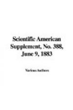
[Illustration: Farcot’s improved Woolf compound engine.]
Details of Construction.—Figs. 1 and 2 represent the motor in vertical section made in the direction of two planes at right angles. Figs. 3 and 4 are horizontal sections made respectively in the direction of the lines 1-2 and 3-4.
The frame, which is of cast iron and entirely hollow, consists of two uprights, B, connected at their upper part by a sort of cap, B¹, which is cast in a piece with the two cylinders, C and c. The whole rests upon a base, B squared, which is itself bolted to the masonry foundation.
Each of the uprights is provided internally with projecting pieces for receiving the guides between which slides the cross-head, g, of the piston rod. The slides terminate in two lubricating cups designed for oiling the surfaces submitted to friction.
The cross-head carries two bearings, g¹, to which is jointed the forked extremity, D, of the connecting rod, whose opposite extremity receives a strap that embraces the cranked end of the driving shaft, A. It will be remarked that the crank, A¹, and the bearings, g¹, are very long. The end the inventor had in view in constructing them thus was to diminish friction.
To the shaft, A, are keyed the coupling disks, Q, which are cast solid at a portion of their circumference situated at 180 deg. with respect to the parts, A squared, of the cranked shaft, the object of this being to balance the latter as well as a portion of the connecting rod, D.
The shaft, A, also receives the eccentric, E, of the slide valve, the rod, e, of which is jointed to the slide valve rod through the intermedium of a cross-head, e¹, analogous to that of the pistons, and which, like the latter, runs on guides held by the support, b.
The two pistons, p and P, are mounted very simply on the rod, T, as shown in Fig. 1, and slide in cylinders, c and C, whose diameters are respectively equal to 270 and 470 millimeters.


