[Illustration: FIG. 2. & FIG. 3.]
By using the third prism in conjunction with the second a still longer base of one-fourth the distance of the object can be employed. The range finder can also be used as a depleidoscope for transit observations. For this purpose it is mounted on a block of wood by means of elastic band and leveled by the level on its lid, being at the same time set in the meridian of the place. The lid is opened to make an angle with the horizon equal to the latitude of the place of observation. On looking into the upper prism two images of the sun will be seen on each side of the apex of the prism, which gradually approach each other as the sun nears the meridian, and finally coincide as it passes it, the time of which being noted gives the longitude of the place.
Extensive trials of the instrument have been made both in this country and in India, which agree in showing that the average error in using the instrument is about 21/2 to 31/2 per cent.
* * * * *
WHEELS LINKED WITH A BELL CRANK.
[Illustration: FIG. 1]
There are four ways in which a connecting rod is made use of in machine work. The first is in linking two wheels together that stand in the same position, but a slight distance off centers. The rod in this case has only to lead the driven wheel around by connecting it with the driver, and consequently has only to endure a pulling strain in the direction of its length. The second is when the rod is called upon to stand a pull and a push at every revolution. The third takes in the matter of the twisting strain that a rod can manage; but the fourth brings the hardest usage that a connecting rod can be called upon to endure, and that is by making a lever of the rod to get a driving action by prying on a fulcrum in the center. In Fig. 1 is seen a case of this kind taken from a machine in which a disk engine was made use of. The rod has a chance to turn about on its center from a ball and socket joint, and engages with both wheels in nicely fitted journals, and boxes set in line with the center of the socket joint, so that when one wheel turns, the rod pries the other around by using the rod as a lever and the ball joint for a fulcrum, giving a uniform leverage all the while, with no dead centers.
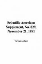
[Illustration: FIG. 2.]
To set this arrangement around at right angles, or where the shafts will bring the wheels together, as for bevel gears, a bent lever arm would need to be used, as shown in Fig. 2, but the bend in the connecting arms brings in another feature that must be provided, as it allows the wheels to turn either with or against each other, and leaves two places where the bent arms will come to a dead center. What is needed here is another element that will take all the twisting strain on the rod and keep the pitch of both arms alike in every portion of a revolution. To do this


