Fig. 1 is a side elevation. Fig. 2 is a vertical cross section.
[Illustration: Fig. 1.]
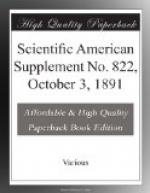
[Illustration: Fig. 2.]
A represents the main driving shaft or axle, driven constantly and at a uniform speed, and B is the pinion-supporting case or shell, mounted loosely on and revoluble around the axle, but held normally at rest by means of a locking bolt, C, or other suitable locking device adapted to enter notches, c, in the shell.
D is the primary driving pinion, fixed firmly to the axle and constantly engaging the pinion, E, mounted on a stud in the shell. The pinion, E, is formed integral with or firmly secured to the smaller secondary pinion, F, which in turn constantly engages and drives the center pinion, G, mounted to turn loosely on the axle within the shell, so that it is turned in the same direction as the axle, but at a slower speed.
F’, F_{2}, F_{3}, F_{4}, etc., represent additional secondary pinions grouped around the center pinion, mounted on studs in the shell, and made of different diameters, so that they are driven by the center pinion at different speeds. Each of the secondary pinions is formed with a neck or journal, f, projected out through the side of the shell, so that the external pinion, H, may be applied to any one of the necks at will in order to communicate motion thence to the gear, I, which occupies a fixed position, and from which the fertilizer or other mechanism is driven.
In order to drive the gear, I, at one speed or another, as may be demanded, it is only necessary to apply the pinion, H, to the neck of that secondary pinion which is turning at the appropriate speed and then turn the shell bodily around the axle until the external pinion is carried into engagement with gear I, when the shell is again locked fast. The axle communicates motion through D, E, and P to the center pinion, which in turn drives all the secondary pinions except F. If the external pinion is applied to F, it will receive motion directly therefrom; but if applied to either of the secondary pinions, it will receive motion through or by way of the center pinion. It will be seen that all the pinions are sustained and protected within the shell.
The essence of the invention lies in the introduction of the pinions D and E between the axle and the series of secondary pinions to reduce the speed.
* * * * *
ELECTRICAL STANDARDS.
Nature states that the Queen’s Printers are now issuing the Report (dated July 23, 1891) to the President of the Board of Trade, of the Committee appointed to consider the question of constructing standards for the measurement of electricity. The committee included Mr. Courtenay Boyle, C.B., Major P. Cardew, R.E., Mr. E. Graves, Mr. W.H. Preece, F.R.S., Sir W. Thomson, F.R.S., Lord Rayleigh, F.R.S., Prof. G. Carey Foster, F.R.S., Mr. R.T. Glazebrook, F.R. S., Dr. John Hopkinson, F.R.S., Prof. W.E. Ayrton, F.R.S.


