Shearing specimens are frequently cut from beams after testing. In this case the specific gravity (dry), proportion of late wood, and rate of growth are assumed to be the same as already recorded for the beams. In specimens not so taken, these quantities are determined in the usual way. The sheared-off portion is used for a moisture section.
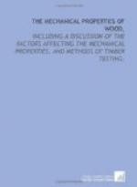
Adjusting specimen in machine: The test specimen is placed in the shearing apparatus with the tenon or lip under the sliding plate, which is centred under the movable head of the machine. (See Fig. 39.) In order to reduce to a minimum the friction due to the lateral pressure of the plate against the bearings of the slot, the apparatus is sometimes placed upon several parallel steel rods to form a roller base. A slight initial load is applied to take up the lost motion of the machinery, and the beam balanced.
[Illustration: FIG. 39.—Making a shearing test.]
Log of the test: The load is applied continuously and at a uniform rate until failure, but no deformations are measured. The points noted are the maximum load and the length of time required to reach it. Sketches are made of the failure. If the failure is not pure shear the test is culled.
The shearing strength per square inch is found by
dividing the
{
P }
maximum load by the cross-sectional area. { Q = —–
}
{
A }
IMPACT TEST
Apparatus: There are several types of impact testing machines.[59] One of the simplest and most efficient for use with wood is illustrated in Figure 40. The base of the machine is 7 feet long, 2.5 feet wide at the centre, and weighs 3,500 pounds. Two upright columns, each 8 feet long, act as guides for the striking head. At the top of the column is the hoisting mechanism for raising or lowering the striking weights. The power for operating the machine is furnished by a motor set on the top. The hoisting-mechanism is all controlled by a single operating lever, shown on the side of the column, whereby the striking weight may be raised, lowered, or stopped at the will of the operator. There is an automatic safety device for stopping the machine when the weight reaches the top.
[Footnote 59: For description of U.S. Forest Service automatic and autographic impact testing machine, see Proc. Am. Soc. for Testing Materials, Vol. VIII, 1908, pp. 538-540.]
[Illustration: FIG. 40.—Impact testing machine.]
The weight is lifted by a chain, one end of which passes over a sprocket wheel in the hoisting mechanism. On the lower end of the chain is hung an electro-magnet of sufficient magnetic strength to support the heaviest striking weights. When it is desired to drop the striking weight the electric current is broken and reversed by means of an automatic switch and current breaker. The height of drop may be regulated by setting at the desired height on one of the columns a tripping pin which throws the switch on the magnet and so breaks and reverses the current.


